· by Jason Miller
Basic VXLAN Config
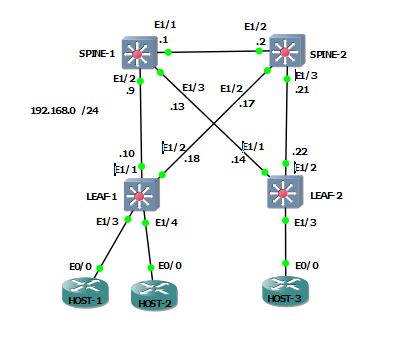
We will be setting up a very basic VXLAN config using the below topology to allow HOSTS 1 – 3 to communicate with each other directly. For this i’m using Cisco’s Nexus 9000v within GNS3. Instructions for getting the 9000v are located here
Setting up the underlay
First we need to enable the features required. The spines will only need OSPF and multicast enabled. OSPF is needed to ensure reachability to all of the VTEP (VXLAN Tunnel Endpoint) interfaces and multicast is how the VTEPs will transmit BUM (Broadcast, Unknown Unicast, and Multicast) traffic.
# SPINE-1 and 2
feature pim
feature ospf
# LEAF-1 and 2
feature pim
feature ospf
feature vn-segment-vlan-based
feature nv overlayNext we need to configure OSPF and then assign the LEAF switches a new VTEP /32 loopback and advertise into OSPF. OSPF’s router ID will be set to the pre-configured loopback0 interface. OSPF interface type will be set to point-to-point.
# SPINE-1
router ospf 100
 router-id 192.168.255.1
int lo0
 ip router ospf 100 area 0.0.0.0
int eth1/2
 description LINK TO LEAF-1
 ip ospf network point-to-point
 ip router ospf 100 area 0.0.0.0
int eth1/3
 description LINK TO LEAF-2
 ip ospf network point-to-point
 ip router ospf 100 area 0.0.0.0

# SPINE-2
router ospf 100
 router-id 192.168.255.2
int lo0
 ip router ospf 100 area 0.0.0.0
int eth1/2
 description LINK TO LEAF-1
 ip ospf network point-to-point
 ip router ospf 100 area 0.0.0.0
int eth1/3
 description LINK TO LEAF-2
 ip ospf network point-to-point
 ip router ospf 100 area 0.0.0.0
# LEAF-1
router ospf 100
router-id 192.168.255.3
int eth1/1
description LINK to SPINE-1
ip ospf network point-to-point
ip router ospf 100 area 0.0.0.0
int eth1/2
description LINK to SPINE-2
ip ospf network point-to-point
ip router ospf 100 area 0.0.0.0
int lo10
description VTEP INTERFACE
ip address 192.168.254.1 255.255.255.255
ip router ospf 100 area 0.0.0.0
# LEAF-2
router ospf 100
router-id 192.168.255.4
int eth1/1
description LINK to SPINE-1
ip ospf network point-to-point
ip router ospf 100 area 0.0.0.0
int eth1/2
description LINK to SPINE-2
ip ospf network point-to-point
ip router ospf 100 area 0.0.0.0
int lo10
description VTEP INTERFACE
ip address 192.168.254.2 255.255.255.255
ip router ospf 100 area 0.0.0.0LEAF-1# sh ip ospf nei
OSPF Process ID 100 VRF default
Total number of neighbors: 2
Neighbor ID Pri State Up Time Address Interface
192.168.255.1 1 FULL/ - 16:00:52 192.168.0.9 Eth1/1
192.168.255.2 1 FULL/ - 16:00:53 192.168.0.17 Eth1/2
LEAF-2# sh ip ospf nei
OSPF Process ID 100 VRF default
Total number of neighbors: 2
Neighbor ID Pri State Up Time Address Interface
192.168.255.1 1 FULL/ - 00:00:28 192.168.0.13 Eth1/1
192.168.255.2 1 FULL/ - 00:00:26 192.168.0.21 Eth1/2Next we will configure multicast. The spines will be acting as the anycast RPs, so they’ll need another loopback and advertise it into OSPF. Then we’ll enable pim on all relevant interfaces.
# SPINE-1
int lo1
 description ANYCAST IP
 ip add 192.168.254.199 255.255.255.255
 ip router ospf 100 area 0.0.0.0
 ip pim sparse-mode
int eth1/2 - 3
 ip pim sparse-mode
 exit
ip pim rp-address 192.168.254.199
ip pim anycast-rp 192.168.254.199 192.168.255.1
ip pim anycast-rp 192.168.254.199 192.168.255.2

# SPINE-2
int lo1
 description ANYCAST IP
 ip add 192.168.254.199 255.255.255.255
 ip router ospf 100 area 0.0.0.0
 ip pim sparse-mode
int eth1/2 - 3
 ip pim sparse-mode
 exit
ip pim rp-address 192.168.254.199
ip pim anycast-rp 192.168.254.199 192.168.255.1
ip pim anycast-rp 192.168.254.199 192.168.255.2
And the config on the Leafs
int lo10
 ip pim sparse-mode
int eth1/1 - 2
 ip pim sparse-mode
 exit
ip pim rp-address 192.168.254.199
Verify PIM neighbors
LEAF-1# sh ip pim nei
PIM Neighbor Status for VRF "default"
Neighbor        Interface            Uptime    Expires   DR       Bidir-  BFD
                                                         Priority Capable State
192.168.0.9     Ethernet1/1          16:26:21  00:01:33  1        yes     n/a
192.168.0.17    Ethernet1/2          16:26:17  00:01:23  1        yes     n/a


LEAF-2# sh ip pim nei
PIM Neighbor Status for VRF "default"
Neighbor        Interface            Uptime    Expires   DR       Bidir-  BFD
                                                         Priority Capable State
192.168.0.13    Ethernet1/1          16:26:03  00:01:19  1        yes     n/a
192.168.0.21    Ethernet1/2          16:26:02  00:01:44  1        yes     n/a
Now for a quick test. Configure LEAF-2 to join the group 239.1.1.1 on its VTEP interface and try to ping it from LEAF-1
# LEAF-2
int lo10
 ip igmp join-group 239.1.1.1

# LEAF-1
LEAF-1# ping multicast 239.1.1.1 interface Eth1/1
PING 239.1.1.1 (239.1.1.1): 56 data bytes
64 bytes from 192.168.0.14: icmp_seq=0 ttl=253 time=23.054 ms
64 bytes from 192.168.0.14: icmp_seq=1 ttl=253 time=9.512 ms
64 bytes from 192.168.0.14: icmp_seq=2 ttl=253 time=7.537 ms
64 bytes from 192.168.0.14: icmp_seq=3 ttl=253 time=4.975 ms
64 bytes from 192.168.0.14: icmp_seq=4 ttl=253 time=4.267 ms
Setting up the VXLAN overlay
Now for the fun part. First we create the user vlan and VNI (VXLAN Network ID), and then map that to a NVE (Network Virtual Endpoint) interface and then toss the hosts into the vlan.
# LEAF-1 and LEAF-2
vlan 100
  vn-segment 100
!
int nve1
  source-interface loopback10
  member vni 100 mcast-group 239.1.1.1
  no shut
!
int HOST_INTERFACES
 switchport access vlan 100
Verification
You may need to send traffic through before the details below show up
LEAF-1# sh nve int nve1
Interface: nve1, State: Up, encapsulation: VXLAN
 VPC Capability: VPC-VIP-Only [not-notified]
 Local Router MAC: 0007.fa5d.db07
 Host Learning Mode: Data-Plane
 Source-Interface: loopback10 (primary: 192.168.254.3, secondary: 0.0.0.0)
!
LEAF-1# sh nve peer detail
Details of nve Peers:
----------------------------------------
Peer-Ip: 192.168.254.4
    NVE Interface       : nve1
    Peer State          : Up
    Peer Uptime         : 00:02:52
    Router-Mac          : n/a
    Peer First VNI      : 100
    Time since Create   : 00:02:52
    Configured VNIs     : 100
    Provision State     : add-complete
    Route-Update        : Yes
    Peer Flags          : None
    Learnt CP VNIs      : --
    Peer-ifindex-resp   : Yes
----------------------------------------


LEAF-2# sh nve int nve1
Interface: nve1, State: Up, encapsulation: VXLAN
 VPC Capability: VPC-VIP-Only [not-notified]
 Local Router MAC: 0007.fab5.5f07
 Host Learning Mode: Data-Plane
 Source-Interface: loopback10 (primary: 192.168.254.4, secondary: 0.0.0.0)
!
LEAF-2# sh nve peer detail
Details of nve Peers:
----------------------------------------
Peer-Ip: 192.168.254.3
    NVE Interface       : nve1
    Peer State          : Up
    Peer Uptime         : 00:05:58
    Router-Mac          : n/a
    Peer First VNI      : 100
    Time since Create   : 00:05:58
    Configured VNIs     : 100
    Provision State     : add-complete
    Route-Update        : Yes
    Peer Flags          : None
    Learnt CP VNIs      : --
    Peer-ifindex-resp   : Yes
----------------------------------------
Now to send some pings from HOST-1 to HOST-3 which are on separate LEAF nodes
HOST-1: 192.168.10.10
HOST-2: 192.168.10.20
HOST-3: 192.168.10.30
HOST-1#ping 192.168.10.30
Type escape sequence to abort.
Sending 5, 100-byte ICMP Echos to 192.168.10.30, timeout is 2 seconds:
!!!!!
Success rate is 100 percent (5/5), round-trip min/avg/max = 6/8/12 ms
!
HOST-1#sh ip arp eth0/0
Protocol  Address          Age (min)  Hardware Addr   Type   Interface
Internet  192.168.10.10           -   aabb.cc00.0200  ARPA   Ethernet0/0
Internet  192.168.10.20           4   aabb.cc00.0300  ARPA   Ethernet0/0
Internet  192.168.10.30           4   aabb.cc00.0400  ARPA   Ethernet0/0